Guidance on GPR and general electromagnetic modelling
In order to make the most of gprMax for modelling GPR you should be familiar with the Finite-Difference Time-Domain (FDTD) method on which the gprMax software is based.
This section discusses some basic concepts of the FDTD method and its application to GPR modelling. Most of the concepts also apply to general electromagnetic modelling, and some newer features may be more useful in other applications than GPR. There is a large body of relevant FDTD literature. Good starting points are [KUN1993] and [TAF2005], as well as Professor Schneider’s Understanding the Finite-Difference Time-Domain Method. The application of FDTD to the GPR forward problem is described in detail in [GIA1997].
Basic concepts
All electromagnetic phenomena, on a macroscopic scale, are described by the well-known Maxwell’s equations. These are first order partial differential equations which express the relations between the fundamental electromagnetic field quantities and their dependence on their sources.
where \(t\) is time (seconds) and \(q_v\) is the volume electric charge density (coulombs/cubic metre). In Maxwell’s equations, the field vectors are assumed to be single-valued, bounded, continuous functions of position and time. In order to simulate the GPR response from a particular target or set of targets the above equations have to be solved subject to the geometry of the problem and the initial conditions.
The nature of the GPR forward problem classifies it as an initial value – open boundary problem. This means that in order to obtain a solution you have to define an initial condition (i.e. excitation of the GPR transmitting antenna) and allow for the resulting fields to propagate through space reaching a zero value at infinity since, there is no specific boundary which limits the geometry of the problem and where the electromagnetic fields can take a predetermined value. Although the first part is easy to accommodate (i.e. specification of the source), the second part cannot be easily tackled using a finite computational space.
The FDTD approach to the numerical solution of Maxwell’s equations is to discretize both the space and time continua. Thus the discretization spatial \(\Delta x\), \(\Delta y\) and \(\Delta z\) and temporal \(\Delta t\) steps play a very significant role – since the smaller they are the closer the FDTD model is to a real representation of the problem. However, the values of the discretization steps always have to be finite, since computers have a limited amount of storage and finite processing speed. Hence, the FDTD model represents a discretized version of the real problem and is of limited size. The building block of this discretized FDTD grid is the Yee cell [YEE1966] named after Kane Yee who pioneered the FDTD method. This is illustrated for the 3D case in Fig. 1.
Notice in Fig. 1 that all electromagnetic field components are staggered in space and time. The electric field components are assumed to be located at the edges of the Yee cell and the magnetic field components at the faces of the cell. The time staggering is such that the electric field components are updated at integer time steps and the magnetic field components at half-integer time steps. This staggering is essential for the numerical stability of the FDTD method. In reality the Yee cell is not a real structure representing a physical object, but rather a mathematical construct which is used to represent the electromagnetic field components in space and time. The Yee cell is the basic building block of the FDTD grid and the electromagnetic fields are calculated at each cell in the grid at their location. Objects are represented in the FDTD grid by assigning appropriate constitutive parameters to the locations of the electromagnetic field components.
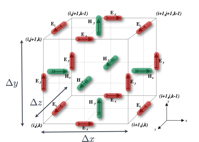
Fig. 1 Single FDTD Yee cell showing electric (red) and magnetic (green) field components.
By assigning appropriate constitutive parameters to the locations of the electromagnetic field components complex shaped targets can be included easily in the models. However, objects with curved boundaries are represented using a staircase approximation.
gprMax is fundamentally based on solving Maxwell’s equations in 3D. However, some problems can be solved in 2D when the geometry and sources are invariant along one Cartesian axis. Maxwell’s equations then reduce to a simpler set that is computationally less expensive to solve. For example, a Hertzian dipole represents a line source in a 2D problem.
gprMax supports both two-dimensional transverse-magnetic (TM) and transverse-electric (TE) reductions. A reduced 3D Yee-grid structure is used so that model descriptions remain consistent between 2D and 3D. TM models are one cell thick on the invariant axis, whereas TE models are two cells thick. This internal representation is transparent to the user.
The recommended input is to declare #domain_mode: TM or
#domain_mode: TE and write inf for
the invariant component of #domain. The inf token identifies the
invariant direction; it does not allocate an infinite grid. gprMax represents
TM with one internal cell and TE with two internal cells on that axis, as
required by the Yee staggering. The older one-cell-domain convention remains
available and selects TM mode. The 2D TMz and TEz arrangements are illustrated
in Fig. 2 and Fig. 3, respectively.
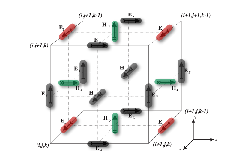
Fig. 2 Single FDTD Yee cell showing electric (red), magnetic (green), and zeroed out (grey) field components for 2D transverse magnetic (TM) z-direction mode.
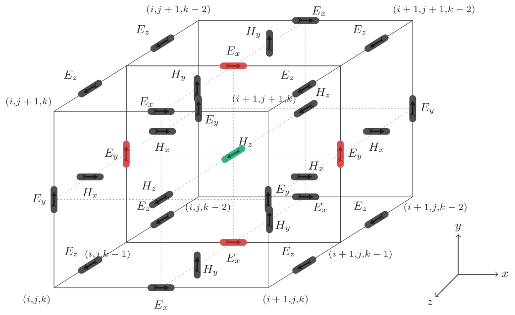
Fig. 3 Two FDTD Yee cells showing the 2D transverse electric (TE) z-direction mode. The active \(E_x\), \(E_y\), and \(H_z\) components (red and green) lie on the shared interior plane. Their inactive values on the two outer boundary planes, together with the suppressed \(E_z\), \(H_x\), and \(H_y\) components, are grey. The outer planes provide the PEC/PMC closure required by the Yee staggering.
Using this approach means that Maxwell’s equations in 3D, shown in (1) as six coupled partial differential equations, reduce to three coupled equations. The TMz system is shown in (2), and the complementary TEz system in (3).
For an invariant x or y axis, the component labels are permuted accordingly. Sources, receivers, snapshots, material construction, and geometry outputs use only the components active in the selected 2D system. Unsupported source polarisations and features are rejected during model construction.
These equations are discretized in both space and time and applied in each FDTD cell. The numerical solution is obtained directly in the time domain in an iterative fashion. In each iteration, the electromagnetic fields advance (propagate) in the FDTD grid and each iteration corresponds to an elapsed simulated time of one \(\Delta t\). Hence by specifying the number of iterations you can instruct the FDTD solver to simulate the fields for a given time window.
The price you have to pay for obtaining a solution directly in the time domain using the FDTD method is that the values of \(\Delta x\), \(\Delta y\), \(\Delta z\) and \(\Delta t\) can not be assigned independently. FDTD is a conditionally stable numerical process. The stability condition is known as the CFL condition after the initials of Courant, Freidrichs and Lewy and is given by,
where \(c\) is the speed of light. Hence \(\Delta t\) is bounded by the values of \(\Delta x\), \(\Delta y\) and \(\Delta z\). The stability condition for the 2D case is easily obtained by letting \(\Delta z \longrightarrow \infty\).
Coordinate system and conventions
A right-handed Cartesian coordinate system is used with the origin of space coordinates in the lower left corner at (0,0,0). Fig. 4 illustrates the coordinate system of gprMax. Only one row of cells in the x direction is depicted. The space coordinates range from the left edge of the first cell to the right edge of the last one. Assuming that \(\Delta x = 1\) metre, if you wanted to allocate a rectangle with its x dimension equal to 3 metres and its lower x coordinate at 1 then the x range would be [1..4]. The 3D cells allocated by gprMax would be [1..3]. In the 3D FDTD cell there are no field components located at the centre of the cell. Electric field components are tangential to, and magnetic field components normal to the interfaces between cells. The field components depicted in Fig. 4 correspond to space coordinate 1. Source and output points defined in space coordinates are directly converted to cell coordinates and the corresponding field components.
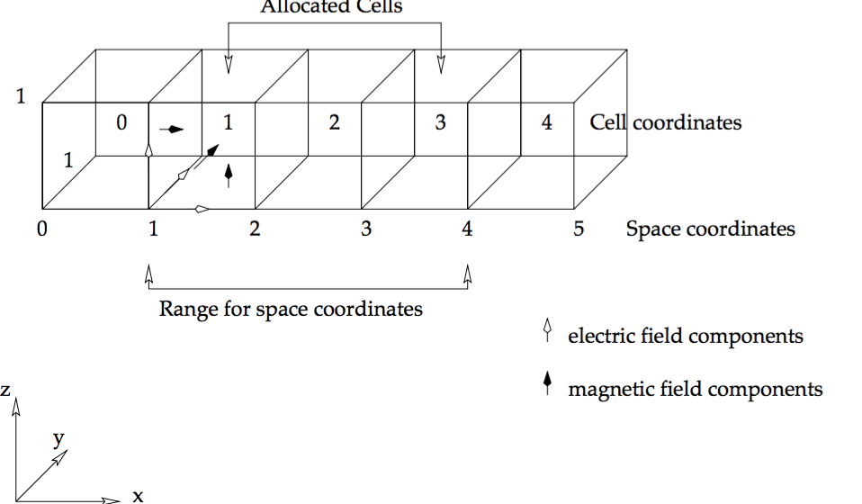
Fig. 4 gprMax coordinate system and conventions.
The actual positions of field components for a given set of space coordinates (x, y, z) are:
Hertzian dipole sources as well as other electric field excitations (i.e. voltage sources, transmission lines) are located at the corresponding electric field components.
Spatial discretization
There is no specific guideline for choosing the right spatial discretization for a given problem. In general, it depends on the required accuracy, the frequency content of the source pulse and the size of the targets. Obviously, all targets present in a model must be adequately resolved. This means, for example, that a cylinder with radius equal to one or two spatial steps does not really look like a cylinder!
Another important factor that influences the spatial discretization is the error associated with numerically induced dispersion. Unlike the physical world, where electromagnetic waves propagate at the same velocity irrespective of direction and frequency (assuming nondispersive media and far-field conditions), this is not true on the discrete grid. This error (details can be found in [GIA1997] and [KUN1993]) can be kept to a minimum if the following rule-of-thumb is satisfied:
The discretization step should be at least ten times smaller than the shortest wavelength of the propagating electromagnetic fields; for better accuracy, use a step that is 20 times smaller.
Note that in general low-loss media wavelengths are much smaller compared to free space.
Absorbing boundary conditions
One of the most challenging issues in modelling open boundary problems, such as GPR, is the truncation of the computational domain at a finite distance from sources and targets where the values of the electromagnetic fields can not be calculated directly by the numerical method applied inside the model. Hence, an approximate condition known as absorbing boundary condition (ABC) is applied at a sufficient distance from the source to truncate and therefore limit the computational space. The role of this ABC is to absorb any waves impinging on it, hence simulating an unbounded space. The computational space (i.e the model) limited by the ABCs should contain all important features of the model such as sources and output points and targets. Fig. 5 illustrates this basic difference between the problem to be modelled and the actual FDTD modelled space.
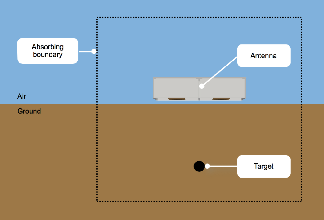
Fig. 5 GPR forward problem showing computational domain bounded by Absorbing Boundary Conditions (ABCs)
It is assumed that the half-space which contains the target(s) is of infinite extent. Therefore, the only reflected waves will be the ones originating from the target. In cases where the host medium is not of infinite extent (e.g. a finite concrete slab) the assumption of infinite extent can be made as far as the actual reflections from the slab termination are not of interest or its actual size is large enough that any reflected waves which will originate at its termination will not affect the solution for the required time window. In general, any objects that span the size of the computational domain (i.e. model) are assumed to extend to infinity. The only reflections which will originate from their termination at the truncation boundaries of the model are due to imperfections of the ABCs and in general are of a very small amplitude compared with the reflections from target(s) inside the model.
The ABCs employed in gprMax will, in general, perform well (i.e. without introducing significant artificial reflections) if all sources and targets are kept at least 15 cells away from them. gprMax uses a stretched-coordinate Perfectly Matched Layer (PML). In a PML, the spatial derivative in each Cartesian direction \(u\) is modified according to
where the elementary complex-frequency-shifted (CFS) stretching function is
The conductivity-like parameter \(\sigma_u\) controls attenuation within the layer, \(\kappa_u\) provides real coordinate scaling, and the complex-frequency shift \(\alpha_u\) improves the absorption of low-frequency and evanescent fields. These parameters are normally graded from the interface with the physical domain towards the outer boundary so that the numerical impedance change is gradual.
gprMax implements the CFS-PML using recursive integration (RIPML). The frequency-dependent terms are represented in the time domain by recursively updated, field-dependent electric and magnetic currents. These currents are applied only within the PML as corrections after the standard FDTD electric- and magnetic-field updates. Consequently, the fields do not have to be split, and the same implementation can be applied without changing the update equations of the underlying material. The general recursive-integration formulation supports multiple CFS terms [GIA2012].
Two ways of combining the CFS terms are available. The Higher-Order RIPML (HORIPML) uses the product
whereas the Multipole RIPML (MRIPML) uses the additive stretching function
The multipole formulation was introduced by Giannopoulos [GIA2018]. Its additive construction avoids the additional cross terms generated when elementary stretching functions are multiplied in a higher-order PML. This makes the role of each CFS pole clearer during optimisation, while retaining good broadband and late-time absorption. Each additional pole requires one additional recursive memory variable per stretched-coordinate field derivative. gprMax currently supports first- and second-order configurations; its default is a first-order CFS RIPML.
The cells of the RIPML, which have a user adjustable thickness, very efficiently absorb most waves that propagate in them. Although, source and output points can be specified inside these cells it is wrong to do so from the point of view of correct modelling. The fields inside these cells are not of interest to GPR modelling. Placing sources inside these cells could have effects that have not been studied and will certainly provide erroneous results from the perspective of GPR modelling. The requirement to keep sources and targets at least 15 cells away for the PML has to be taken into account when deciding the size of the model domain. Additionally, free space (i.e. air) should be always included above a source for at least 15-20 cells in GPR models. Obviously, the more cells there are between observation points, sources, targets and the absorbing boundaries, the better the results will be.
gprMax offers advanced users control over the PML formulation, the thickness on each boundary, and the grading profile, direction, minimum, and maximum values of \(\alpha\), \(\kappa\), and \(\sigma\) for each CFS term. This permits optimisation for specific applications. Experimental one-axis PML slabs can also be placed as local matched loads inside PEC guiding structures or used to replace an individual boundary PML. These slabs reuse the same RIPML formulations and CFS profiles, require a constant material extrusion, and support domain-decomposed MPI CPU models. By default, an internal slab automatically creates its four transverse PEC walls and maximum-stretch backing plate while leaving its zero-stretch entrance open. This enclosure can be disabled for advanced experiments, in which case exposed faces generate warnings and require case-specific stability testing. For command syntax and the associated stability restrictions see the PML commands or the Python API.
All other boundary conditions which apply at interfaces between different media in the FDTD model are automatically enforced in gprMax.